LEDs Description
The E-SBC module provides LEDs for indicating various operating status, as described in the following table.
E-SBC Module LEDs
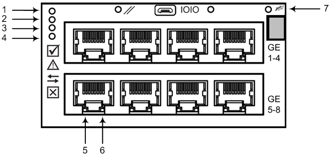
E-SBC Module LEDs Description
|
Item # |
LED |
Color |
State |
Description |
|---|---|---|---|---|
|
1 |
|
Green |
On |
Module in service |
|
- |
Off |
Module out of service |
||
|
2 |
|
- |
Off |
During booting up state |
|
Red |
On |
Booting up phase / fault detected in module |
||
|
Green |
On |
Normal operation |
||
|
3 |
|
- |
Off |
During booting up state |
|
Green |
On |
Indicates that the device is in Standalone mode (not High Availability / HA). |
||
|
Flashing |
Indicates that the device is in HA mode. Note: This color state appears only on the Active device. |
|||
|
Yellow |
On |
Indicates that the Redundant device is still not synchronized with the Active device for HA. Note: This color state appears only on the Redundant device. |
||
|
Flashing |
Indicates that the Redundant device is synchronized with the Active device for HA. Note: This color state appears only on the Redundant device. |
|||
|
4 |
|
Red |
On |
Out of service |
|
- |
Off |
Normal operation |
||
|
5 |
Left LED on Ethernet Ports |
Green |
On |
Ethernet link established. |
|
Flashing |
Data is being received or transmitted (activity) on the Ethernet port. |
|||
|
- |
Off |
No Ethernet link. |
||
|
6 |
Right LED on Ethernet Ports |
Orange |
On |
1000Base-T (Gigabit) Ethernet link established. |
|
- |
Off |
No Ethernet link or 100Base-Tx link established. |
||
|
7 |
|
Blue |
On |
Blue hot-swap LED indicating that the AMC module can be fully removed or inserted. Note: Do not remove the module before this LED turns blue. |
|
- |
Off |
The module insertion process is complete. |


